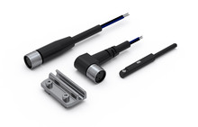
Magnetic field sensors
Magnetic Field Sensors, Cables and Sensor Holder for MCE & MSCE
| Designation | Select all | CAD | Compare | Get quote | Lead Time * | Description | Ball Screw (d x l) | Dynamic Load Capacity C (N) | Max. Drive Torque Mₚ (Nm) | Max. Travel Speed Vmax (m/s) | Max. Rotational Speed nmax (min⁻¹) (rev/min) | No Load Torque M₀ (Nm) | Axial Dynamic Load Capacity Ca (N) | Max. Permissible Axial Load Fpa (N) | Max. Permissible Payload Horizontal mph (kg) | Max. Permissible Payload Vertical mpv (kg) | Max. Permissible Radial Load on Shaft Fpr (N) | Dynamic Moment Mx (Nm) | Dynamic Moment My (Nm) | Dynamic Moment Mz (Nm) | Max. Permissible Loads Forces Fpy (N) | Max. Permissible Loads Forces Fpz (N) | Max. Permissible Loads Moments Mpx (Nm) | Max. Permissible Loads Moments Mpy (Nm) | Max. Permissible Loads Moments Mpz (Nm) | Moved Mass (kg) | Mass of the Mini Electric Slider mMSCE (kg) | Mass Moment of Inertia JMSCE (10⁻² kg cm²) | Planar Moment of Inertia ly (cm⁴) | Planar Moment of Inertia lz (cm⁴) | |
|---|---|---|---|---|---|---|---|---|---|---|---|---|---|---|---|---|---|---|---|---|---|---|---|---|---|---|---|---|---|---|---|
|
|
|
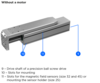
2 | Without motor | 6 × 2 mm | 1310 | 0.06 | 0.150 | 4500 | 0.03 | 1900 | 170 | 57 | 14 | 25 | 4.8 | 4.1 | 4.1 | 280 | 580 | 4.8 | 4.1 | 4.1 | 0.10 + 0.0010 × Abs. stroke | 0.20 + 0.0019 × Abs. stroke | 0.29 + 0.0007 × Abs. stroke + 0.1013 × mload | 0.08 (slide) / 2.10 (base profile) | 0.88 (slide) / 1.98 (base profile) | ||||
|
|
|
2 | Without motor | 6 × 6 mm | 1310 | 0.1 | 0.450 | 4500 | 0.03 | 1700 | 90 | 30 | 7 | 25 | 4.8 | 4.1 | 4.1 | 280 | 580 | 4.8 | 4.1 | 4.1 | 0.10 + 0.0010 × Abs. stroke | 0.20 + 0.0019 × Abs. stroke | 0.36 + 0.0016 × Abs. stroke + 0.9119 × mload | 0.08 (slide) / 2.10 (base profile) | 0.88 (slide) / 1.98 (base profile) | ||||
|
|
|
2 | Without motor | 8 × 2 mm | 2135 | 0.13 | 0.150 | 4500 | 0.05 | 2000 | 375 | 125 | 31 | 50 | 10 | 6.8 | 6.8 | 860 | 860 | 10 | 6.8 | 6.8 | 0.18 + 0.0013 × Abs. stroke | 0.40 + 0.0032 × Abs. stroke | 0.71 + 0.0026 × Abs. stroke + 0.1013 × mload | 0.18 (slide) / 6.42 (base profile) | 2.16 (slide) / 6.58 (base profile) | ||||
|
|
|
2 | Without motor | 8 × 8 mm | 2135 | 0.53 | 0.600 | 4500 | 0.06 | 1500 | 375 | 125 | 31 | 50 | 10 | 6.8 | 6.8 | 860 | 860 | 10 | 6.8 | 6.8 | 0.18 + 0.0013 × Abs. stroke | 0.40 + 0.0032 × Abs. stroke | 0.99 + 0.0047 × Abs. stroke + 1.6211 × mload | 0.18 (slide) / 6.42 (base profile) | 2.16 (slide) / 6.58 (base profile) | ||||
|
|
|
2 | Without motor | 10 × 3 mm | 3240 | 0.37 | 0.225 | 4500 | 0.08 | 3500 | 695 | 233 | 58 | 100 | 20.1 | 17.4 | 17.4 | 1000 | 1000 | 16.3 | 16.3 | 16.3 | 0.36 + 0.0025 × Abs. stroke | 0.88 + 0.0059 × Abs. stroke | 2.81 + 0.0061 × Abs. stroke + 0.2280 × mload | 0.40 (slide) / 25.37 (base profile) | 7.34 (slide) / 25.16 (base profile) | ||||
|
|
|
2 | Without motor | 10 × 10 mm | 3240 | 1.23 | 0.750 | 4500 | 0.10 | 3200 | 695 | 233 | 58 | 100 | 20.1 | 17.4 | 17.4 | 1000 | 1000 | 16.3 | 16.3 | 16.3 | 0.36 + 0.0025 × Abs. stroke | 0.88 + 0.0059 × Abs. stroke | 3.63 + 0.0121 × Abs. stroke + 2.5330 × mload | 0.40 (slide) / 25.37 (base profile) | 7.34 (slide) / 25.16 (base profile) |
*Green: Normally in stock, contact us for current status. Blue: Contact us for delivery time.
| Designation | Select all | CAD | Compare | Get quote | L1 | L2 | L3 | L4 | L5 | L6 | L7 | L8 | L9 | L10 | L11 | L12 | L13 | L14 | L15 | L16 | L17 | L18 | L19 | L20 | L21 | L22 | L23 | U1 | U2 | U3 | U4 | U5 | |
|---|---|---|---|---|---|---|---|---|---|---|---|---|---|---|---|---|---|---|---|---|---|---|---|---|---|---|---|---|---|---|---|---|---|
|
|
|
50 | 12 | 6 | 6 | Ø 12 | 36.5 | 58 | 25 | 13.5 | 19.25 | 4.4 | 19 | 17 | 18 | Ø M2.5 | 8 | 14 | 7 | Ø 5 (h7) | Ø 17.6 | Ø 20 (h7) | 4.5 | 2.3 | 2.2 | 4.2 | 2.8 | 1.4 | 1 | ||||
|
|
|
50 | 12 | 6 | 6 | Ø 12 | 36.5 | 58 | 25 | 13.5 | 19.25 | 4.4 | 19 | 17 | 18 | Ø M2.5 | 8 | 14 | 7 | Ø 5 (h7) | Ø 17.6 | Ø 20 (h7) | 4.5 | 2.3 | 2.2 | 4.2 | 2.8 | 1.4 | 1 | ||||
|
|
|
65 | 14 | 8 | 6 | Ø 14 | 45 | 73 | 32 | 13.5 | 22.8 | 4.4 | 24.5 | 24.5 | 24.5 | Ø M3 | 8 | 14 | 7 | Ø 5 (h7) | Ø 22.6 | Ø 25 (h7) | 4.5 | 2.3 | 3.2 | 5.8 | 3.6 | 2 | 1 | ||||
|
|
|
65 | 14 | 8 | 6 | Ø 14 | 45 | 73 | 32 | 13.5 | 22.8 | 4.4 | 24.5 | 24.5 | 24.5 | Ø M3 | 8 | 14 | 7 | Ø 5 (h7) | Ø 22.6 | Ø 25 (h7) | 4.5 | 2.3 | 3.2 | 5.8 | 3.6 | 2 | 1 | ||||
|
|
|
80 | 18 | 10 | 8 | Ø 18 | 60.5 | 91 | 45 | 20 | 30.5 | 4.4 | 34 | 34 | 34 | Ø M4 | 10 | 16 | 8 | Ø 8 (h7) | Ø 31.6 | Ø 34 (h7) | 4.5 | 2.3 | 4.2 | 7.5 | 4.7 | 2.5 | 1.2 | ||||
|
|
|
80 | 18 | 10 | 8 | Ø 18 | 60.5 | 91 | 45 | 20 | 30.5 | 4.4 | 34 | 34 | 34 | Ø M4 | 10 | 16 | 8 | Ø 8 (h7) | Ø 31.6 | Ø 34 (h7) | 4.5 | 2.3 | 4.2 | 7.5 | 4.7 | 2.5 | 1.2 |